Everything You Need to Know About the PCI Express – Hardware Secrets
Since the first PC, launched in 1981, the computer has had expansion slots where you can install additional cards to add capabilities not available on the motherboard of the computer. Currently, the most common type of expansion slot available is called PCI Express. In this tutorial, you will learn everything you need to know about this kind of connection: how it works, versions, slots, and more.
Before talking about the PCI Express, we must talk a little bit about the history of PC expansion slots and their main challenges, so you can understand what makes the PCI Express different.
[amazon box=”B01G86538S” template=”table”]
Below we list the most common types of expansion slots that were launched for the PC throughout its history:
- ISA (Industry Standard Architecture)
- MCA (Micro Channel Architecture)
- EISA (Extended Industry Standard Architecture)
- VLB (VESA Local Bus)
- PCI (Peripheral Component Interconnect)
- PCI-X (Peripheral Component Interconnect eXtended)
- AGP (Accelerated Graphics Port)
- PCI Express (Peripheral Component Interconnect Express)
New kinds of expansion slots are released whenever available slot types are proved to be too slow for certain applications. For example, the original ISA slot available on the original IBM PC and on the IBM PC XT and their clones, had a maximum theoretical transfer rate (i.e., bandwidth) of only 4.77 MB/s (4.77 MHz transferring eight bits per clock cycle). The 16-bit version of the ISA, launched with the IBM PC AT in 1984, almost doubled the available bandwidth to 8 MB/s (8 MHz transferring 16 bits each two clock cycles; each access cycle on the ISA bus takes two clock pulses to be completed), but this number was extremely low even at the time for high-bandwidth applications such as video.
Then IBM released the MCA slot for its PS/2 computer line, and because it was copyrighted, other manufacturers could only use it if they entered a licensing scheme with IBM, and only five companies have done so (Apricot, Dell, Tandy, Research Machines, and Olivetti). So, the MCA slots were confined to a few PC models from these brands. Nine PC manufacturers joined to create the EISA slot, but it wasn’t successful for two reasons. First, it maintained compatibility with the original ISA slot, so its clock rate was the same as the 16-bit ISA slot. Second, the alliance didn’t include motherboard manufacturers, so do-it-yourself users and other manufacturers didn’t have access to this slot, the same way it had happened with the MCA slot.
The first real high-speed slot to be released was the VLB. The higher speed was achieved by tying the slot to the CPU local bus, i.e., the CPU external bus. This way, the slot worked at the same speed as the CPU external bus, which is the fastest bus available on the PC. In the table below, we are listing this slot as using a 33 MHz clock rate, but the actual clock rate will depend on the CPU used. (Most CPUs at the time used a 33 MHz external clock rate, but CPUs with 25 MHz and 40 MHz external clock rates were also available.) The problem with this bus was that it was designed specifically for the local bus of 486-class processors. When the Pentium processor was released, it was incompatible with it, as it used a local bus with different specifications (66 MHz external clock rate instead of 33 MHz and 64-bit data transfers instead of 32-bit).
he first industry-wide solution appeared in 1992, when Intel lead the industry to create “the definitive” expansion slot, the PCI. Later, other companies joined the alliance, which is known today as PCI-SIG (PCI Special Interest Group). The PCI-SIG is responsible for standardizing the PCI, PCI-X and PCI Express slots. By the way, some laypeople have difficulty making a distinction between PCI, PCI-X, and PCI Express (“PCIe”). Even though these names are similar, they refer to completely different technologies.
The PCI is a platform-independent bus that is connected to the system using a bridge chip (which is part of the motherboard chipset). Whenever a new CPU is released, you can still use the same PCI bus by redesigning the bridge chip instead of redesigning the bus, which was the norm before the PCI bus was created.
A bus is a data path where you can attach several devices at the same time, sharing this data path. The most obvious devices attached to the PCI bus were expansion slots, but integrated components available on the motherboard such as an on-board network chip could be connected to the PCI bus.
Even though other configurations were theoretically possible, the most common implementation of the PCI bus was with a clock with 33 MHz with a 32-bit data path, enabling a bandwidth of 133 MB/s.
The PCI-X bus is a version of the PCI bus working at higher clock rates and with wider data paths for server motherboards, achieving higher bandwidth for devices that demanded more speed, such as high-end network cards and RAID controllers.
When the PCI bus proved to be too slow for high-end video cards, the AGP slot was developed. This slot was used exclusively for video cards.
Then, finally, the PCI-SIG developed a connection called PCI Express (formerly known as “3GIO” and officially abbreviated as “PCIe,” although most people abbreviate it, incorrectly, as “PCI-E”). Despite its name, PCI Express works radically different from the PCI bus.
- PCI is a bus, whereas PCI Express is a point-to-point connection, i.e., it connects only two devices; no other device can share this connection. Just to clarify, on a motherboard using standard PCI slots, all PCI devices are connected to the PCI bus and share the same data path, so a bottleneck (i.e., performance decrease because more than one device wants to transmit data at the same time) may occur. On a motherboard with PCI Express slots, each PCI Express slot is connected to the motherboard chipset using a dedicated lane, not sharing this lane (data path) with other PCI Express slots. Also, devices integrated on the motherboard, such as network, SATA, and USB controllers, are usually connected to the motherboard chipset using dedicated PCI Express connections.
- PCI and all other kinds of expansion slots use parallel communications, while PCI Express is based on high-speed serial communications.
- PCI Express is based on individual lanes, which can be grouped to create higher-bandwidth connections. The “x” that follows the description of a PCI Express connection refers to the number of lanes that connection is using.
The PCI Express connection is the subject of this tutorial. We will go into more detail about how it works in the following pages.
Below is a table comparing the main specifications for the expansion slots that ever existed for the PC.
SlotClockNumber of BitsData per Clock CycleBandwidthISA4.77 MHz814.77 MB/sISA8 MHz160.58 MB/sMCA5 MHz16110 MB/sMCA5 MHz32120 MB/sEISA8.33 MHz32133.3 MB/s (16.7 MB/s typically)VLB33 MHz321133 MB/sPCI33 MHz321133 MB/sPCI-X 6666 MHz641533 MB/sPCI-X 133133 MHz6411,066 MB/sPCI-X 266133 MHz6422,132 MB/sPCI-X 533133 MHz6444,266 MB/sAGP x166 MHz321266 MB/sAGP x266 MHz322533 MB/sAGP x466 MHz3241,066 MB/sAGP x866 MHz3282,133 MB/sPCIe 1.0 x12.5 GHz11250 MB/sPCIe 1.0 x42.5 GHz411,000 MB/sPCIe 1.0 x82.5 GHz812,000 MB/sPCIe 1.0 x162.5 GHz1614,000 MB/sPCIe 2.0 x15 GHz11500 MB/sPCIe 2.0 x45 GHz412,000 MB/sPCIe 2.0 x85 GHz814,000 MB/sPCIe 2.0 x165 GHz1618,000 MB/sPCIe 3.0 x18 GHz111,000 MB/sPCIe 3.0 x48 GHz414,000 MB/sPCIe 3.0 x88 GHz818,000 MB/sPCIe 3.0 x168 GHz16116,000 MB/s
[nextpage title=”From Parallel to Serial”]
The PCI Express connection represents an extraordinary advance in the way peripheral devices communicate with the computer. It differs from the PCI bus in many aspects, but the most important one is the way data is transferred. The PCI Express connection is another example of the trend of migrating data transfer from parallel communication to serial communication. Other common interfaces that use the serial communication include the USB, the Ethernet (networking), and the SATA and SAS (storage).
Before the PCI Express, all PC buses and expansion slots used parallel communication. In parallel communication several bits are transferred on the data path at the same time, in parallel. In serial communication, only one bit is transferred on the data path per clock cycle. At first, this makes parallel communication faster than serial communication, since the higher the number of bits transmitted at a time, the faster the communication will be.
Parallel communication, though, suffers from some issues that prevent transmissions from reaching higher clock rates. The higher the clock, the greater will be the problems with electromagnetic interference (EMI) and propagation delay.
When electric current flows through a wire, an electromagnetic field is created around it. This field may induce electrical current on the adjacent wire, corrupting the information being transmitted on it. As in parallel transmission, several bits are transmitted at a time, each bit involved in the transmission using one wire. For example, in a 32-bit communication (such as the standard PCI slot) it is necessary to have 32 wires just to transmit data, not counting additional control signals that are also necessary. The higher the clock, the greater the electromagnetic interference problem.

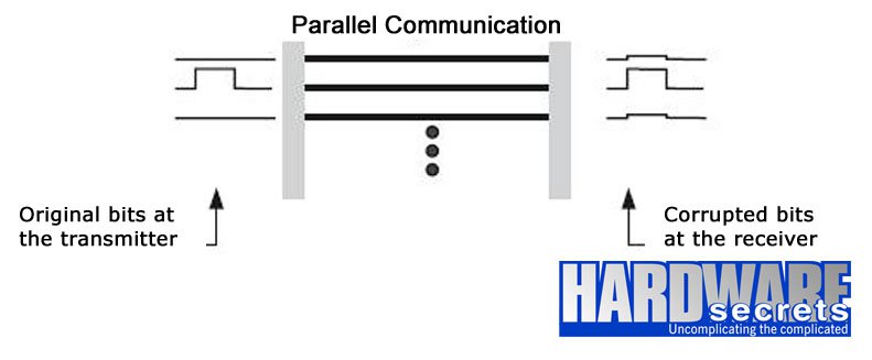
Figure 1: Bits arrive at the receptor that was corrupted due to electromagnetic interference
As we have commented before, each bit in parallel communication is transmitted on a separate wire, but it is almost impossible to make those 32 wires have exactly the same length on a motherboard. At higher clock rates, data transmitted through shorter wires arrive before the data that are transmitted through longer wires. That is, the bits in parallel communication may arrive delayed. As a consequence, the receiving device must wait for all the bits to arrive in order to process the complete data, which represents a significant loss in performance. This problem is known as propagation delay and becomes worse with the increase in the clock rates.
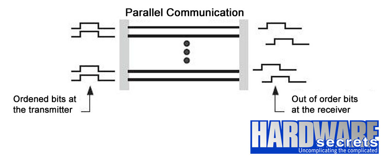
Figure 2: Bits out of order arrive at the receptor due to propagation delay
The project of a communications bus using serial communication is simpler to implement than one using parallel communication since fewer wires are necessary to transmit data. On a typical serial communication, four wires are necessary – two for transmitting data and two for receiving, usually with a technique against electromagnetic interference called cancellation or differential transmission. With the cancellation, the same signal is transmitted on two wires, with the second wire transmitting the signal “mirrored” (inverted polarity) compared to the original signal, as you can see in Figure 3. When the receiver gets the signal, it can compare the two signals, which must be equal but “mirrored.” The difference between the two signals is noise, making it very simple for the receiver to know what noise is and to discard it.
Figure 3: Cancellation technique
Besides providing higher immunity to electromagnetic interference, serial communications don’t suffer from propagation delays. This way, they can achieve higher clock rates more easily than parallel communications.
Another very important difference between parallel communication and serial communication is that parallel communication is usually half-duplex (the same wires are used to transmit and to receive data) due to the high number of wires that are necessary for its implementation. Serial communication is full-duplex (there is a separate set of wires to transmit data and another set of wires to receive data) because it needs just two wires each way. With a half-duplex communication, two devices can’t talk to each other at the same time; either one or the other is transmitting data. With full-duplex communication, both devices can be transmitting data at the same time.
These are the main reasons why engineers adopted serial communication instead of parallel communication with the PCI Express.
Now you might be asking yourself, “Isn’t serial communication slower?” It depends on what you are comparing. If you compare a parallel communication of 33 MHz transmitting 32 bits per clock cycle, it will be 32 times faster than a serial communication of 33 MHz transmitting only one bit at a time. However, if you compare the same parallel communication to a serial communication working at a much higher clock rate, the serial communication may be, in fact, much faster. Just compare the bandwidth of the original PCI bus, which is 133 MB/s (33 MHz x 32 bits), with the lowest bandwidth you can achieve with a PCI Express connection (250 MB/s, 2.5 GHz x 1 bit).
The notion that serial is “always” slower than parallel communication comes from old computers that had ports called “serial port” and “parallel port.” At that time, the parallel port was much faster than the serial port. That was because of the way these ports were implemented. This doesn’t mean that serial communications are always slower than parallel communications.
Let’s now talk about how the PCI Express communication works.
[nextpage title=”Operation Modes”]
The PCI Express connection is based on the concept of a “lane,” which is a single-bit, full-duplex, high-speed serial communication. Lanes can be grouped to increase bandwidth. For example, when two devices use four lanes for their connection, they are considered an “x4” connection and will be able to achieve four times more bandwidth than a single connection, i.e., a single lane. In Figure 4, we illustrate two connected devices using two lanes, i.e., an “x2” connection. Although in theory any number from one to 32 lanes can be grouped, the most common numbers are x4, x8, and x16.
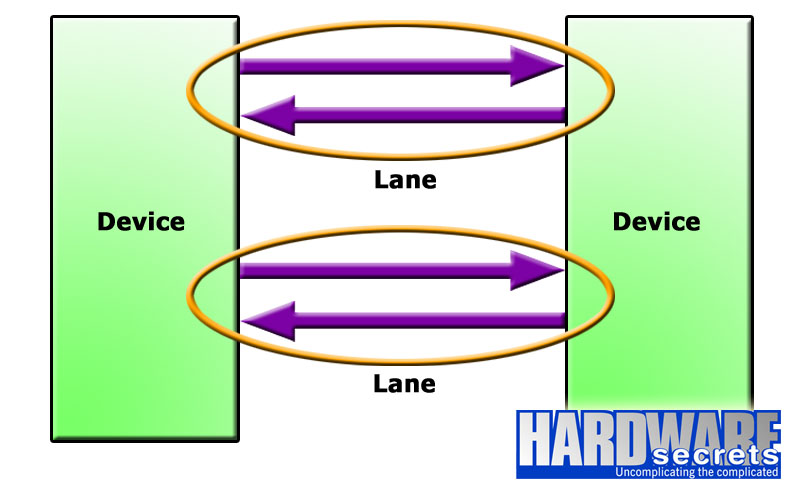
Figure 4: PCI Express x2 connection
PCI Express 1.0 and 2.0 use the 8b/10b encoding system (which is the same encoding used by Fast Ethernet, i.e., 100 Mbps, networks). This means that every eight bits of data are encoded and transmitted as a 10-bit number. Usually, to convert a figure given in bits per second (bps) to bytes per second (B/s) you need to divide it by eight since a byte is a group of eight bits. However, because of the 8b/10b encoding, we need to make this division by 10 rather than eight. This is the reason why, with a clock of 2.5 GHz and 5 GHz, the x1 bandwidth of these connections is 250 MB/s and 500 MB/s, respectively, and not 312.5 MB/s and 625 MB/s. The two extra bits added are called “overhead,” and they “eat” 20% of the channel bandwidth.
PCI Express 3.0 uses a different encoding system, called 128b/130b. As you can deduce, this encoding system transmits every 128 bits of data as a 130-bit number, which offers a far lower overhead. To transmit 128 bits of data, PCI Express 3.0 needs only two extra bits, while with the previous revisions, 32 extra bits are needed (two for every eight bits). Because of this lower overhead requirement, PCI Express 3.0 can achieve double the PCI Express 2.0 bandwidth with a clock rate of 8 GHz instead of 10 GHz.
PCI Express 4.0, which will be released in a couple of years, will maintain the same encoding as PCI Express 3.0, doubling the clock rate and, therefore, doubling the available bandwidth.
RevisionEncodingClockBandwidth (x1)1.08b/10b2.5 GHz250 MB/s2.08b/10b5 GHz500 MB/s3.0128b/130b8 GHz1 GB/s4.0128b/130b16 GHz2 GB/s
As explained, the grouping of lanes allows the bandwidth to be multiplied by the number of lanes used. So, an x8 connection with PCI Express 2.0 will have a bandwidth of 4 GB/s (500 MB/s x 8), while an x16 connection with PCI Express 2.0 will have a bandwidth of 8 GB/s (500 MB/s x 16). An x16 connection with PCI Express 3.0 will have a bandwidth of 16 GB/s (1 GB/s x 16).
[nextpage title=”Slots and Cards”]
The PCI Express specification allows slots to have different physical sizes, depending on the number of lanes connected to the slot. See Figure 5. This allows reducing the size of the space needed on the motherboard. For example, if a slot with an x1 connection is required, the motherboard manufacturer can use a smaller slot, saving space on the motherboard.
However, bigger slots can actually have fewer lanes than the diagram shown in Figure 5. For example, many motherboards have x16 slots that are connected to x8, x4, or even x1 lanes. With bigger slots, it is important to know if their physical sizes really correspond to their speeds. Moreover, some slots may downgrade their speeds when their lanes are shared. The most common scenario is on motherboards with two or more x16 slots. With several motherboards, there are only 16 lanes connecting the first two x16 slots to the PCI Express controller. This means that when you install a single video card, it will have the x16 bandwidth available, but when two video cards are installed, each video card will have x8 bandwidth each.
[amazon box=”B01MQ5R7I1″ template=”table”]
The motherboard manual should supply this information. But a practical tip is to look inside the slot to see how many contacts it has. If you see that the contacts on a PCI Express x16 slot are reduced to half of what they should be, this means that even though this slot is physically an x16 slot, it actually has eight lanes (x8). If with this same slot you see that the number of contacts is reduced to a quarter of what it should have, you are seeing an x16 slot that actually has only four lanes (x4). It is important to understand that not all motherboard manufacturers follow this; some still use all contacts even though the slot is connected to a lower number of lanes. The best advice is to check the motherboard manual for the correct information.
A little-known fact is that you can install any PCI Express expansion card in any PCI Express slot. For example, you can install an x1 expansion card in any kind of PCI Express slot; it doesn’t need to be installed in an x1 slot. So, if you have an x4 expansion card but your motherboard doesn’t have an x4 PCI Express slot, no problem; simply install it in an x8 or x16 slot.
The same holds true for “bigger” cards. For example, you can install an x16 video card in a “smaller” slot. (The slot, however, must have its rear side open; otherwise, the bigger expansion card won’t fit. It is up to the motherboard manufacturer whether or not to provide slots with their rear side open.) The only disadvantage is that it will only have the maximum bandwidth provided by the slot; i.e., if you install an x16 video card in an x4 slot, it will have only x4 bandwidth available. On the other hand, this kind of installation may be useful in some situations, such as when building a computer with several video cards to have multiple displays available, and you are not worried about gaming performance.
To reach the maximum performance possible, both the expansion card and the PCI Express controller (available inside the CPU or inside the motherboard chipset, depending on your system) have to be of the same revision. If you have a PCI Express 2.0 video card and install it on a system with a PCI Express 3.0 controller, you will be limited to the PCI Express 2.0 bandwidth. The same video card installed on an old system with a PCI Express 1.0 controller will be limited to the PCI Express 1.0 bandwidth.
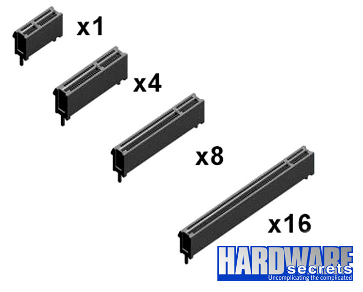
Figure 5: Types of PCI Express slots
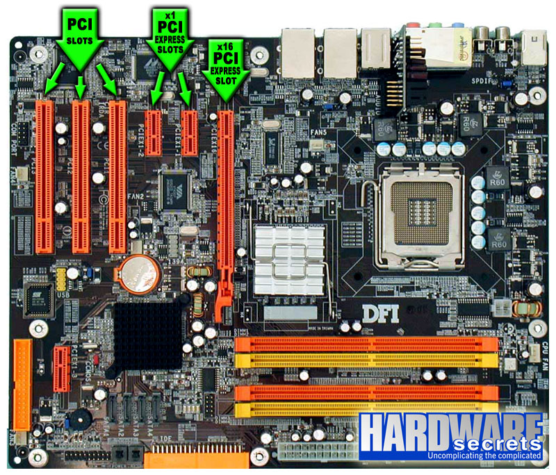
Figure 6: Details of the PCI and PCI Express slots on a motherboard
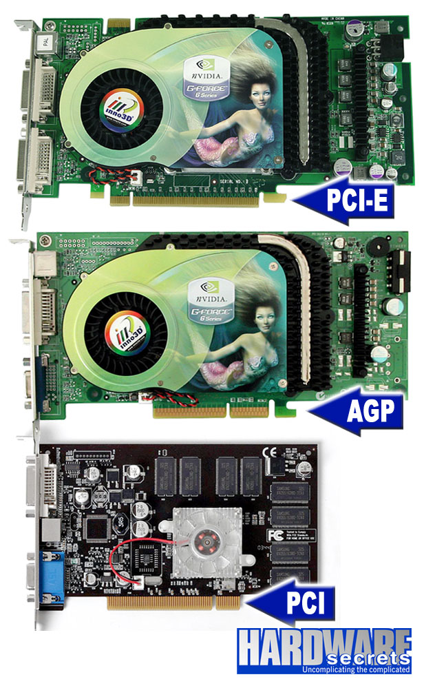
Figure 7: Differences in the edge contacts of PCI Express, AGP, and PCI video cards
What Are the Differences Between AGP and PCIe Graphics Cards?
The primary difference between AGP and PCI Express graphic cards is the dissimilar ports that they come with. AGP cards also tend to be a lot slower and PCIe cards, which is the reason why gamers and video editors tend to avoid AGP entirely.
However, the AGP’s legacy cannot be contested. This specific type of card was developed by Intel and was at an all-time high in popularity during the early 2000s. How so? Well, AGP was made specifically for 3D graphics and gaming, which is quite ironic seeing that today no gamer or 3D designer even thinks about buying an AGP card.
Now that we’ve got the main grip out of the way, let’s see what other notable differences there are between AGP and PCI Express cards.
- Contrary to your intuition and logic, PCI Express cards did not replace PCI cards. Instead, PCI cards got replaced by AGP cards and then AGP cards got replaced by PCI Express video cards. Now that’s a mouthful!
- Another key difference is their interface: AGP is dedicated, point to point, whilst PCIe is a two-way serial connection.
- Furthermore, the distance between the card’s bracket and the start of the connector is greater on AGP cards and much smaller on PCIe cards.
- You’ll also find that the slots on the motherboard for each one are different – AGP slots are usually brown while PCIe slots are white or other more attractive colors.
- When it comes to the overclocking speed, AGP goes up to 8x while PCIe can go double – up to 16x.
The Bottom Line
Now you’ve learned probably all there is to know about PCI Express graphics cards. If you have any other inquiries on this topic, feel free to leave us a comment below and start a discussion with the rest of our community.